


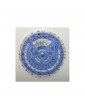
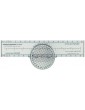


The Rogers Data navigation compass 500 combines sectional plotter, time-speed-distance computer, ruler and navigation compass template in a single device. The Rogers Data navigation compass facilitates the solution of path-time measurement for charts on the scale of 1:500.000 and is easy to use.
Distance measurement:
In order to read the distance between two points on a sectional chart, the scale at the top of the front side of the Rogers Data navigation compass must be used. On the scale below the mark the distances in NM (nautical miles) picked up with the tips of the two legs of the navigation compass can be read. Conversely, distances on the navigation compass can be set and transmitted into a sectional chart by means of the tips.
Flight time:
In order to determine the time of flight use the tips of the navigation compass to pick up the distance between two waypoints. Subsequently, read the time
required in minutes for your intended speed on the mounted concentric circles scale below the abel.
Heading:
To determine the heading use the Rogers Data navigation compass with the back positioned on a sectional chart in such a way that the leg with the aircraft symbol comes to rest on the course line and the aircraft symbol and the line with the word „<Intended Track“ shows in the desired direction of flight. The second leg is to be rotated in such a way that the line drawn through the entire middle of the navigation compass and the lines are parallel to a meridian in the sectional chart and the word „Meridian North>“ defines true north. The heading is shown on the mark readable exactly to one degree.
Opposite track:
The opposite track can easily be determined in a single step with the previously described method for determining the heading. Read the opposite track on the Rogers Data navigation compass at the designated „Opposite Track“ Marker where it meets the scale.
Speed measurement:
The groundspeed can be determined when using the Rogers Data navigation compass in combination with a sectional chart. The time for a distance covered is known and the route is taken from the sectional chart by means of the tips of the navigation compass. For this purpose, the known time on the mounted concentric compass scale below the label must be determined and assigned to the respective speed.
Path-time measurement:
When speed and distance are known the time needed for this distance can be derived by using the scales on the front side of the navigation compass. In addition, when speed and time elapsed are known the exact position on the sectional chart as well as the time remaining can be determined.
Direction finding for the determination of bearing and position:
To determine a base line in respect to a bearing of a VOR use the back of the Rogers Data navigation compass with the mark set exactly to the degree on the compass rose. The navigation compass is to be set with the leg positioned on the sectional chart so that the compass rose is oriented to magnetic north of the VOR, considering the variation in the location of the VOR, respectively. Furthermore, the navigation compass is to be positioned so that the center line of the leg with the aircraft symbol aims beyond the radio navigation aid in the direction of the base line. Is a DME distance also known, the position on the base line can be determined. Set the distance in such a way that the mark meets the distance on the scale NM (nautical miles). Now, the accurate position along the base line can be set by means of the tips. If the bearings of two radio navigation aids are known, the position above the intersection of the two base lines can be determined – regarding VORs taking into account the variation of the location of a VOR; regarding NDBs taking into account the variation of the estimated position of the aircraft.
Circle template and ruler:
The upper region of the leg holds a hole with a diameter of 10mm designed as a circular template. This circular template) is surrounded by a cross line which serves as a centering aid. Using this hole permits track points to be outlined in the sectional chart with a circle. This procedure allows reading the details on the track point and prevents that they are covered by any line. Route points drawn with the circle template are to be connected for further determination. The Rogers Data navigation compass can be used as a ruler along the lateral sides.
Click here to leave a review